Have you ever tried using a security camera wiring diagram? They can be an eyesore to demystify. As a security installer, one of my most common questions from do-it-yourselfers is how in the world do I read these wiring diagrams, especially with the Lorex Poe Camera. These diagrams can be essential to getting the electrical circuit installation right and connecting devices cleanly without faults and good layout planning.
We will go through the Lorex Poe Camera Wiring diagram specifically below.
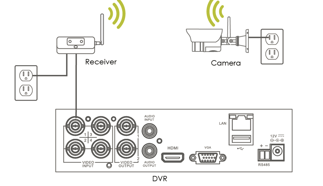
Lorex Poe camera wiring can be done using a few tools. Lorex camera has two varieties including CCTV and IP network camera. CCTV (closed-circuit television) is connected using a 59 coaxial cable, transfers the video, and requires two wires for getting the power. IP (Internet protocol) demands a standard CAT 5 or an Ethernet cable that can be connected to the office network or your home. It is just like the network cable of your computer.
Wiring of CCTV Cameras
- Take the RG-59 cable and connect it to your camera from the security digital video recorder.
- There are some instructions with the BNC connectors so install the BNC on each side of the cable according to the instructions.
- It is advisable to have several types of crimpers and tools to connect the BNC connectors. A specific type of tool is required for installation.
- Plugin the power supply of the camera to the near corner. If you demand to connect the power supply near your security DVR, you can cut the power supply wire in half.
- You can also use Siamese cable power to connect the power supply near your DVR. You can twist the wires together and can use them by covering them with electrical tape or you can use wire nuts.
- There is a dashed line or a rib near the power supply wires. Connect the wires with the black Siamese cable wire and unmarked wire to the red Siamese cable wire.
- Connect the leftover power supply wire to the camera end of the cable. Plugin the power connector to the camera and connect the BNC connector to the camera or security DVR. To fix the wiring cable, you may click here for more information.
Wiring Of an IP Camera
- Follow the instructions given by the camera manufacturer for the required network equipment and plugging. (1)
- Connect and route your CAT 5 or Ethernet cable from your router to the camera, as some camera does not work if they are not plugged into a hub or a switch. (2)
- Install the RJ-45 connector by following the manufacturer’s instructions on each end of the cable.
- Hold the RJ-45 connector away from your body, face it in an upwards direction and keep away the gold contacts. Wire down both connectors through straight-through wiring. Start the wiring from the left to right direction.
- The sequence of the wiring should be from white to orange, orange, white to green, blue, white to blue, green, white to brown, and then brown.
- In the end, plug in your Ethernet cable to the camera and router. Plug the power supply of your camera, and you are done with the whole setup of wiring.
References
(1) network equipment – https://www.sciencedirect.com/topics/engineering/networking-equipment
(2) hub or switch – https://www.tutorialspoint.com/difference-between-hub-and-switch