Buying a new bug detector that’s of high quality can be expensive. Creating one isn’t very easy, but it’s a fun do-it-yourself project, and you can often make better detectors than the cheap ones currently for sale.
This tutorial provides you with what you need and a step-by-step procedure for making your detector. There are two methods to choose from.
Method One
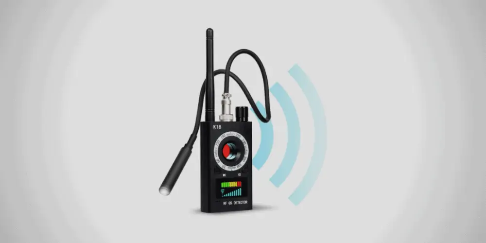
This method will show you how to create an rf detector. These devices detect things that produce radio frequencies; a lot of people think this is a hard device to create, but with a few simple tools, you can make one pretty easily, and we will cover how to do this.
Materials and tools you need on a working table
- BNC connector
- Brass Tube
- Epoxy
- Cotton swab
- 41-AWG enameled copper wire
- Solder
- Screws
- Toothpick
- Wire strippers
- Glue
Step One: Stripping to Expose Wire Ends
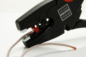
Use a wire stripper to remove the end of the 41- AWG enameled copper wire. The end of this 41-AWG enameled copper wire contains a bit of insulation. It would be best to strip the enameled wire to expose the ends. You should do this process carefully to avoid cutting through the wire. An alternative to this process is to burn the wire end in a small flame to burn off the enamel. When burning the wire, be careful not to overheat it. Otherwise, it will reduce its conductivity.
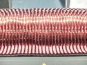
Step Two: Making a Coil
You will need a toothpick at this stage. Use 41-AWG and make a 19-turn coil around the toothpick. Use one end of copper wire to make the rounds.
Step Three: Apply Glue on the Coil
Apply permanent glue on one coil end. You need to ensure that the glue sticks permanently. Take the other end of the wire and run it in a brass tube of 0.09 diameter. Use the wire stripper to strip another 0.5-inch wire from the tube end.
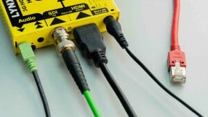
Step Four: Connecting the 41-AWG Copper to the BNC Connector
Connect the 41-AWG copper to the BNC connector. Your tripped wire will have two exposed wires. Solder one wire to a positive (+) of the BNC connector and the other to the negative (-) contact of the BNC connector. (1)
Step Five: Attaching the BNC Connector to the Tube
Use the epoxy to attach the BNC connector to the tube. Apply glue on the cotton swap and rub it on the outer side of the wire coiled around the toothpick.
Step Six: Placing the Toothpick into The Brass Tube
Place the toothpick into the brass tube, then push the glued wire to attach its sides to the brass tube and let it dry.
Step Seven: Screwing the BNC Connector Onto the Female BNC Connector
Take the BNC connector and screw it onto the female BNC connector of the RF voltmeter and then turn it on.
Step Eight: Testing your Detector
Test to find out if it works. Move the brass tube around. If the number displayed on the Radio Frequency voltmeter increases, the detector will spot another bug or an electronic device.
Method 2
The second method is more advanced than the previous one. You need capacitors, transistors, and resistors. It works better than the previous method though you may need some advanced knowledge to finish the task. If you are not well-versed in electronics and do-it-yourself projects, you can find someone to help you connect on the pegboard.
What you need
Inductors
- Ten uH inductor (L2)
- One normal inductor (L1)
Capacitors
- 0.22 uF ceramic disc capacitor (C6-C9) – 4
- 47 uF capacitor (C1) – 1
- A pegboard
Resistors
- 32 ohms resistor (R9) -1
- 220K ohms resistor (R7) – 1
- 1M ohms resistors (R3, R2) –1
- 3.3 ohms resistors (R5, R4) -2
- 47K ohms resistor (R8) -1
- 2.2 ohms resistor (R6) -1
- Bipolar n-p-n transistor for Q1-Q3
- Batteries
- Hot glue gun and the glue
- Buzzer
- LED and diode
- Slide switch
- A bipolar RF transistor for Q4
- Coin cell battery holder
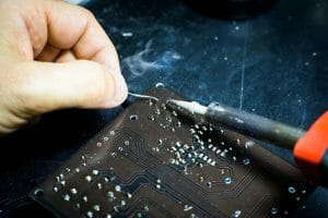
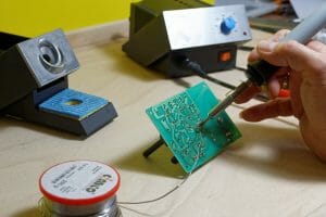
Step One: Setting the Components
Have all the components on the work table and begin by soldering the capacitors. Keep the board in the schematic representation to make the work easy. Someone will have already worked on the schematic drawing.
Step Two: Check the Polarity of the Capacitor
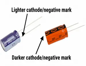
Ensure you check the polarity of the capacitor before working on it. The negative polarity has a silvery stripe on it. Identify this negative polarity and have it on the negative side. Straighten its leads to ensure it fits the board.
Step Three: Inserting the Capacitor
Insert capacitors in their necessary places. Bend the sides of the leads to ensure they are in place, making soldering easy. It makes the setup simpler and will help you back-tracking the design. You can now start soldering the lids.
Step Four: Fixing Resistors
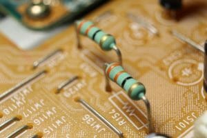
It is time to fix resistors. What should you do? For understanding, there will be marks in different colors on the resistors with values printed on them. Place inductors and resistors on the pegboard and bend them well to ensure they fit correctly in their position. Flip them over and solder their leads. Ensure you arrange everything in the schematic representation for good results.
Step Five: Fixing transistors
Once you have the resistor in place, fix the transistors. Follow the same orientation in the schematic orientation and ensure it does not appear clumsy. Ensure the flat surface faces are left on the board and bend the lead to fit nicely on the board. To make the soldering process easy, bend them on the other side of the board.
Step Six: Fixing the Diode and LED
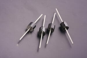
Before fixing the diode and LED, you should understand the tools’ anode and cathode. If you don’t know, don’t worry, it is so easy! Cathodes have a shorter lead and white line on the diode. The cathode should go to the bottom for the LED while to the top for the diode. Also, remember to bend the leads for easy and efficient soldering. (2)
Step Seven: Fixing the Switches
It is time to focus on the switches. Fix them on the board and spread their leads more than others. It will allow them to fit in the right position and make fixing the buzzer easy. Solder their leads like you did for the others before.
Step Eight: Making Turns in the Coil
Get a copper wire and take turns in the coil. You can bend the copper wire on an object with a diameter of 3mm. The turns should be tight. Glue the turns using a hot glue gun. Stripe the end to expose the wires while ensuring you don’t overdo it.
Step Nine: Placing the Battery
You will need to bend two 10mm wires separately to create 2 U-shaped wires. Place them in the Pad 1 area while still following the schematic orientation of the board. Then, place the battery clip in its respective position. Allow for the soldering to happen, and then you will be positioned to place the battery. An antenna is not as complicated as you may think. A wire of 100mm in length can make the antenna.
Step Ten: Soldering the Traces
This is a critical step in this process, as any mistake will affect the setup. Bridge traces that are supposed to be bridged correctly. You can use any excess lead in this step. You can use a piece of wire to ensure the traces are suitable. This step requires your undivided attention.
Step Eleven: Final Setup
Place the complete setup inside the Altoids tin. You should isolate the bottom of the tin to ensure the board does not get short. Create sizeable holes to allow the user to view the switch and the LED. Finally, use the hot glue gun to keep the PCB tightly secured to the tin.
Here’s another learning guide to the DIY bug detector!
References
(1) BNC connector – https://www.pcmag.com/encyclopedia/term/bnc-connector
(2) Cathodes – https://www.thoughtco.com/how-to-define-anode-and-cathode-606452