People who do not want to spend $200 or more on a new bug detector may decide to make a DIY Bug Detector.
The following procedure is enough to have a homemade radio frequency detector while avoiding beginner’s mistakes.
What you will need to follow this tutorial
The elements necessary to make a homemade bug detector are as follows.
- Wire strippers
- 2 x 41 AWG enameled copper wire
- Toothstick
- Glue
- 0.090 in. diameter brass tubing
- BNC connector
- Soldering iron
- Epoxy
- Cotton swab
- RF voltmeter
Once you have the materials, the following steps should be performed.
- Stripping the main cable
- Making a coil
- Applying the glue
- Making the connection
- BNC connector to the brass tube
- Apply the glue and wait
- Incorporating the voltmeter
- Test the device we have created
Step-by-step instructions
1. Stripping the Main Cable
The first step requires a wire stripper to work with the enameled copper wire. One end of the wire should be removed, but both ends should be stripped. The result should be a cable with two ends without the coating and enameled copper exposed. This procedure should be done carefully so as not two damage the enameled copper.
2. Making a Coil

Once you have the 41 AWG enameled copper wire, a 19-turn coil must be made. Only one of the ends of the copper wire should be used for this purpose. (1)
3. Applying the Glue
The user must ensure the coil’s end is perfectly secured to the stick. The appropriate glue must be chosen as not all bonds can work with all material types.
Once the glue has been used, the brass tube, which has an exact diameter of 0.090 inches, must be incorporated. While the first wire thickness does not matter, it helps to consider the thickness of the second wire we need. This wire should be exactly 0.5 inches thick. The wire stripper should be used again to strip one end of the wire.
4. Making the Connection
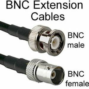
Once the previous step has been completed, the end of the first cable that has been left free should be used. It should be explicitly connected to the 41 AWG copper to the BNC connector. Inside this copper wire, it is possible to see two small cables.
With the BNC connector in mind, one of these wires should be connected to the positive connector. The second wire should be soldered on the negative side of this same connector.
A wide variety of soldering irons can be used. Basic knowledge of soldering irons is required to correctly make the connection between the copper cable and the BNC connector.
5. BNC Connector to the Brass Tube
Once the copper wire is connected to the BNC connector, continue using epoxy. A mistake in this situation is not allowing enough time for this glue to finish the drying process. It can impair the proper functioning of the RF detector we are creating.
The glue should be applied using a cotton swab. Only the necessary glue should be incorporated into the cotton swab before using this.
6. Apply the Glue and Wait
The coiled wire should be added to the brass tube. The copper wires must sufficiently adhere to the sides of the brass tube. It is why you should add a sufficient amount of glue all around the coiled wire. Then wait long enough for the glue to dry completely.
7. Incorporating the Voltmeter
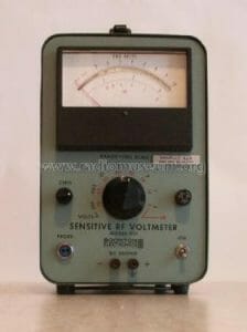
The RF voltmeter must be attached. The BNC connector we have worked with must be screwed to the female BNC connector found on the RF voltmeter. (2)
The voltmeter needs to be turned on. People also can use a multimeter due to its similar functionality to a voltmeter. It should be noted that the multimeter can present a more complex and challenging setup operation for amateurs.
8. Test the Device We Have Created
The necessary test must be performed to detect if our created device works. The user should move the brass tube closer to the devices that produce some radiofrequency devices.
This signal should be visible on the RF voltmeter. The movement should intensify and weaken as the user moves closer or further away from an RF device. The bug detector is working correctly when the audible or visual signal is heard on the RF voltmeter.
Wrapping Up
Did you enjoy this tutorial? Building this homemade device allows people to save money on a professional-level detector. Even having this device is one of the best ways to protect anyone’s privacy at any time.
Aside from making a DIY bug detector, you may check another learning guide on making a bug detector and doing bug detector apps work. Until next time!
Click here to check the best bug detector in the market this year!
References
(1) copper wire – https://www.thomasnet.com/articles/metals-metal-products/types-of-copper-wire/
(2) voltmeter – https://www.britannica.com/science/voltmeter